Connector for ASM to ASM
This section of the documentation describes the details of the ASM connector, including:
- The name of the file used
- Connection methodology
- Use case scenario
- Architectural and functional details that ensure the running of the use case through the Inbound and Outbound action functionality of the Integration Platform
For compatibility and version support details, refer to the ASM Connector Matrix.
You should familiarize yourself with the information in Installing Connectors before installing any connectors, and read the Integration topics for more information on how to configure them.
Overview
The ASM to ASM interoperability concept basically allows for the creation of calls and requests on one ASM System (the Receiver) triggered by actions sent from another ASM System (the Creator).
The type of actions that are implemented and whether calls or requests are logged in the Receiver system is part of the Integration Platform settings in both systems, while creating adequate transactions, ensuring proper communication and maintaining reconciled information between the two systems are amongst the ASM to ASM connector duties.
The connector operation is symmetrical. This means that in some instances one of the systems acts as the Creator, creating calls or requests in the other system, and in other instances the same system acts as the Receiver, calls or requests being created internally based on instructions sent by the other system.
Use Case Scenario
The interoperability concept can be broken down into several use cases that are listed in the table below.
|
Use case |
Notification/Action |
Action taken by Receiver |
Role of the connector |
|
|---|---|---|---|---|
|
Event |
Scenario |
|||
|
Create action |
A call is forwarded externally or an External Supplier Task is sent from the Creator system |
A Create action is initiated. A Create message is sent to the Receiver system. The action is selected by matching the External Supplier and Contract. A note is sent between systems. |
When the Receiver system receives the Create action, it either logs a call or creates a request, depending on the Creator Outbound action set up |
The connector ensures that enough details are transmitted to implement the action defined in the Creator Outbound action. |
|
Call/Request/Task Update |
A call/request/task is updated in the Creator system or a call/request is updated in the Receiver system |
An Update message is sent to the other party. |
Upon receipt of an Update message, the system does one of the following, depending on administrative setup:
|
The connector ensures that enough data are transmitted by the Update message so that any of the listed actions can be performed. |
|
Note attachment |
A note is attached to the call/request/task in the Creator system or a note is attached to the call/request in the Receiver system |
A Notify message is sent to the other party. |
Upon receipt of a Notify message, the system does one of the following depending on administrative setup:
|
The connector ensures that enough data is transmitted by the Notify message so that any of the listed actions can be performed. |
|
Cancel message initiation |
A call is closed, a request or a task is completed, or a call/task is taken back on the Creator system |
A Cancel message is initiated. |
Upon receipt of a Cancel message, the Receiver system does one of the following, depending on the administrative setup:
|
The connector ensures that enough data is transmitted by the Cancel message so that any of the listed actions can be performed. |
|
Complete/Not Complete message creation |
A call is closed or a request is completed in the Receiver system. |
A Complete or Not Complete message is sent from the Receiver system to the Creator system. The Creator system can be configured for the matching call/task to be closed/updated, for a note to be added, or to do nothing.
|
Receiver system sends a Complete message when any one of the following takes place:
Receiver system sends a Not Complete message when any of the following take place:
|
The connector ensures that enough data is transmitted by the Cancel message so that any of the listed actions can be performed by the Creator system. |
Connector Description
The table below provides a description of the Connector for ASM to ASM.
|
Information fields |
Name |
|---|---|
|
Connector name |
ASM Core <-> ASM Core connector |
|
Third-party application |
ASM Core |
Connector Operation
The connector operation makes use of Windows Communication Foundation (WCF). WCF allows for the following:
- Services to be defined abstractly and published physically over a wide variety of channels.
- Permits extensive tailoring of this behavior by updating the appropriate .NET configuration files.
Connector parameter values possess default values that are defined in these configuration files and can be modified. However, possessing a strong knowledge of WCF is a prerequisite before attempting to modify the default parameters.
Endpoint Configuration references a client endpoint configuration by name.
The configuration files also define server endpoints.
Note the following:
- If no name is provided, BasicHttpBinding_ISM2XService is used. This is the name of the default binding defined in the configuration files shipped in the kit.
- It defines how the local ASM instance (client) must communicate with the remote ASM instance (server), as:
- A basic HTTP binding
- References the Infra.Connector.Ionix.SM.ISM2XService service contract
Any changes to the configuration must be applied to the following two files:
- <System>/web.config
- <Root>/Infra.Services.exe.config
Connection Parameters
When setting up a ASM source, the parameters listed below have to be defined.
|
Type of action |
Description |
Connection parameters |
Description |
|---|---|---|---|
|
Outbound actions Third-party application Version developed against |
These settings have to be specified to allow the current system to log calls and/or requests in an external ASM System. |
Endpoint configuration |
References a “client” endpoint configuration by name |
|
Endpoint Address |
http: //<Virtual Server>/<System Name>/SM2XService.svc |
||
|
System |
The name of the system to connect to. This name is identical to the one specified in the Endpoint Address. |
||
|
Login ID |
The ID of an existing user in the Receiver system. This user must have sufficient rights to create calls and/or requests. |
||
|
Password |
The password of the user identified by the Login ID. |
||
|
Inbound actions |
These settings have to be specified to allow an external ASM System to log calls and/or requests in the current system. |
User |
First and last name of an existing person in the current system. |
|
Organization |
An existing organization to which the User belongs. |
In order to successfully connect a system installed on Windows Server 2003 to a system installed on Windows Server 2008, the following steps must be executed on the Windows Server 2008 server:
- Run the following in the command prompt:
"%windir%\Microsoft.NET\Framework\v3.0\Windows Communication Foundation\ServiceModelReg.exe -r -y" - Enable anonymous authentication for the virtual directory in Internet Information Services (IIS).
General Technical Considerations
ASM interoperability between two ASM Systems relies on a specific connector and specific Web Services. Furthermore, the running of the use case scenario requires a specific architecture to be adhered to by the two ASM Systems, as depicted below.
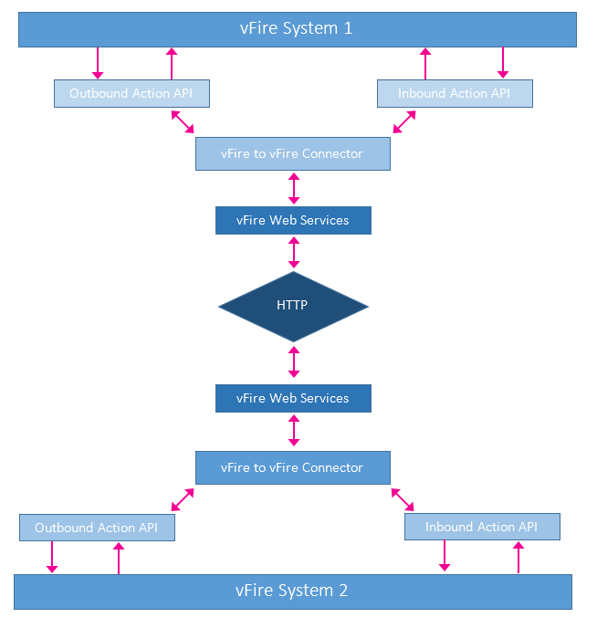
Connector Requirements
The connector ensures:
- A proper connection with the Outbound and Inbound actions APIs of the system it is installed on
- A proper connection with the ASM Services Web of the system it is installed on
- Transfer of communications between the Inbound actions and the Outbound actions APIs of the connected systems
From a functional standpoint, the connector ensures that the message types described in Action and Communication Protocol are properly handled and transferred.
Web Service Details
The Web Service, although not part of the connector itself, is developed especially to support the communication between the two ASM Systems through the connector.
Additional Information
This connector does not include any Federated CMDB population functionality.
Connector Diagnostics
The connector has the facility to trace information. The data can be obtained through Polling tracing or Application tracing.
Inbound/Outbound Actions
This section describes Inbound/Outbound actions and communication protocol handled by the ASM to ASM connector.
Action and Communication Protocol
ASM Interoperability allows calls or requests to be created on one ASM System based on information sent by another. The creation of calls and requests relies on actions being implemented between the two systems. These actions are supported by a particular communication protocol composed of a set of specific transactions, as illustrated below.
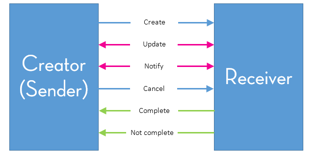
- The Creator sends a Create message to initiate an action for the Receiver to perform.
- Both the Creator and Receiver can send Update messages to each other when required.
- Both the Creator and Receiver can send Notify messages to each other when required.
- The Creator can also send a Cancel message to stop any further processing of the Action by the Receiver.
- A Complete message is sent by the receiver when the action is successfully performed.
- A Not Complete message is sent by the Receiver when the action has not been successfully performed. This does not include failures to establish communication connection with the Receiver.
When two ASM Systems are connected through the ASM to ASM connector, either system can act as the Creator or the Receiver.
Interoperability Operation
To make the ASM to ASM connector available for use, you must:
- Verify the connector service is accessible from each server
- Configure the system(s) for outbound actions
- Configure the system(s) for inbound actions
Follow the steps in both systems to configure ASM System interoperability. For demonstration purposes, we will refer to the systems as System 1 and System 2. If there are specific instructions for systems which are held on different servers, System 1 will be held on Server A and System 2 on Server B.
Verify the Connector Service is Accessible
For demonstration purposes, we will refer to the systems as System 1 and System 2. System 1 will be held on Server A and System 2 on Server B.
For each system, place the endpoint address URL of the other system into a browser and make sure a valid page appears as follows. The endpoint address format is http://Server B/System 2/SM2XService.svc (from Server A) and http://Server A/System 1/SM2XService.svc (from Server B).
In the example below "localhost" indicates that both systems are on the same server.
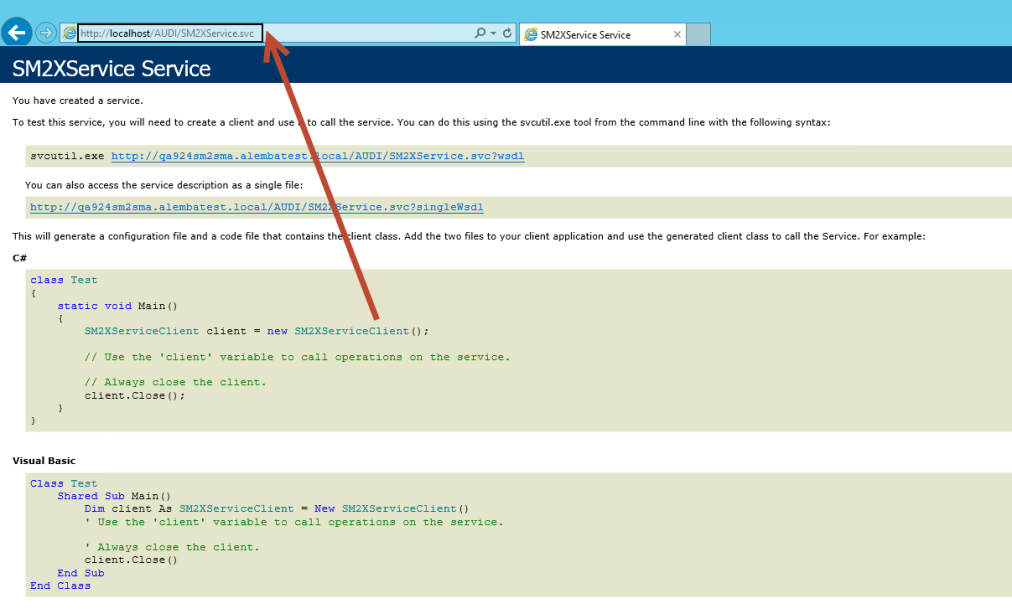
If this page is not returned there may be a blocked port on the firewall. Contact your Network Administration team to resolve.
The ASM to ASM connector requires the configured port to be open on the firewalls between servers, including SOAP/XML messages. The default ports are 80 for http and 443 for https.
Configuring the System for Outbound Actions
For demonstration purposes, we will refer to the outbound system as System 1.
Before you start
The version of the ASM System must be identical on both servers.
There must be an identical Person record on both servers, with Analyst and User permissions. The two records must have the same login ID, and have IPK Analyst selected in the Options tab of their IPK Management security role.
- Log in to ASM System 1.
- Select
 and then Admin. From the submenu, select Integration .
 - Select the Enabled checkbox in Inbound Actions section in the Integration Platform settings and save the details.
- Select the Connectors option from the explorer pane .
- On the Integration Connectors window, locate the ASM to ASM connector, and ensure that the Actions and Visible checkboxes are selected. (You may like to adjust the column widths to see all of the columns.) Save the changes.
The connector is visible in the list of available connectors of the Integration Platform.
- Select the Sources option from the explorer pane .
- Select the
 button on the toolbar. In the pop up window, select ASM to ASM Connector from the drop-down list.
 - In the Integration Source Details window, complete the details.
- If you have already configured the receiving system (System 2), select the
 button on the toolbar to test the connection.
 - Save the details.
- Next, you need to configure the receiving system (if you have not already done so), the outbound actions and the inbound actions.
-
The settings of the Inbound actions of one system influences the possible settings of the Outbound actions of the other system. The possible actions listed in the Outbound actions page of the system for a particular source reflects which Inbound actions have been defined in the specific source system.
| Name | Type the name of the integration source |
| Status | This field is prefilled with the Active status |
| Connector | This field is prefilled with the Connector type |
| Assembly.TypeName | This field is prefilled, based on the selected connector, as defined in the Connector DLL, and is read-only |
| Endpoint Parameters | |
| Endpoint Configuration | Type the following endpoint configuration: BasicHttpBinding_ISM2XService |
| Endpoint Address | Type the endpoint address URL as configured earlier |
| Person Parameters | |
| System | Type the name of the target (receiver) ASM System |
| Login ID | Type the Login ID of the person record which is being used for the connector |
| Password | Type the password of the person record which is being used for the connector |
Further fields are displayed on this window, but you do not need to complete them at this stage.
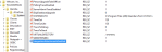
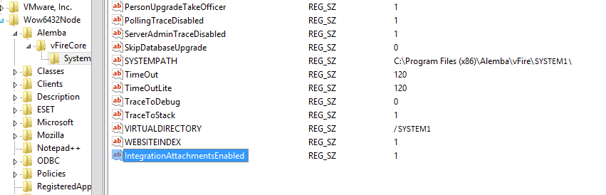
If you want to enable global connector attachments, you must enable them in the registry, using the IntegrationAttachmentsEnabled setting. 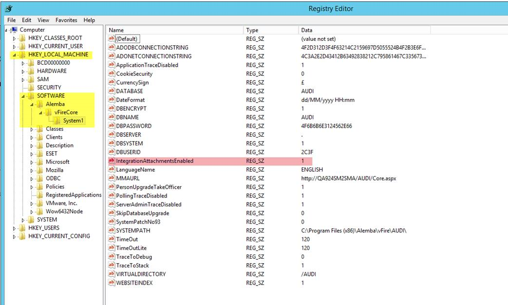
Configuring the System for Inbound Actions
For demonstration purposes, we will refer to the receiving system as System 2.
Before you start
Ensure that the web configuration file has been configured.
- Log in to ASM System 2.
- Select and then Admin. From the submenu, select Integration .
- In the Main Explorer pane under Integration, select Integration Platform Settings to view the settings.
- In the Outbound Actions section, select the Enabled checkbox, then save the details.
- In the Main Explorer pane, select Connectors to view the integration connectors.
-
Locate the ASM to ASM connector, then ensure that the Actions and Visible checkboxes are selected.
Select
 alongside the connector if you need to edit the options. After you have updated the option, select
  to commit the changes to the connector.
(You may like to adjust the column widths to see all of the columns.)
- Select
 to save the changes.
 - In the Main Explorer pane, select Sources.
- Select the button on the toolbar to create a new source.
- In the pop up dialog box, select ASM to ASM Connector from the drop-down list, then select OK.
- In the Integration Source Details window, complete the details.
- If you have already configured the outbound system (System 1), select the button on the toolbar to test the connection.
- Save the integration source configuration.
- After IIS reset on both servers, check the source connection on System 1.
- Next, you need to configure the inbound actions and the outbound actions.
| Name | Type the name of the integration source. |
| Status | Populated with the Active status. |
| Connector | Populated with the Connector type. Read only. |
| Assembly.TypeName | Depends on the selected connector, as defined in the Connector DLL. Read-only. |
| Endpoint Parameters | |
| Endpoint Configuration | Type the following endpoint configuration: BasicHttpBinding_ISM2XService. |
| Endpoint Address | Type the endpoint address URL, as configured earlier. |
| Person Parameters | |
| System | Type the name of the sending (source) ASM System. |
| Login ID | Type the Login ID of the person record that the connector uses to log into ASM. |
| Password | Type the password of the person record that the connector uses to log into ASM. |
If you want to enable global connector attachments, you must enable them in the registry, using the IntegrationAttachmentsEnabled setting.
Configuring the Inbound Actions
You must configure the inbound actions for the connector. The settings of the Inbound actions of one system influences the possible settings of the Outbound actions of the other system. The possible actions listed in the Outbound actions page of the system for a particular source reflects which Inbound actions have been defined in the specific source system.
For demonstration purposes, we will refer to the receiving system as System 2.
- Log in to ASM System 2.
- Select and then Admin. From the submenu, select Integration .
- In the Main Explorer pane under Integration, select Inbound Actions to view the Integration Inbound Actions window.
- Select the button on the toolbar.
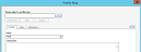
- On the Inbound Action Type Details window, complete the details.
- On the Fields tab, select Add located at the bottom of the window.
- In the Inbound Action Fields pop-up window, scroll down the list of fields in the left hand table and select Call ref and then Add. Then select OK to close the window. The details appear in the table.
- Select
 to close the window. Your new inbound action appears in the Integration Inbound Actions window.
 - Next, you need to configure the outbound actions on the sending system (System 1).
| Name | Type a name for the inbound action |
| Create | Select Call from the drop-down list |
| Using template | Type the template name to find it.. |
Configuring the Outbound Actions
For demonstration purposes, we will refer to the receiving system as System 1.
- Log in to ASM System 1.
- Select and then Admin. From the submenu, select Integration.
- Select Outbound Actions from the explorer pane.
- In the Filter by Source field, select the connector source name from the drop-down list, for example System 1.
- All available outbound actions are listed in the browse table. Select the one you want to work with and then select
 .
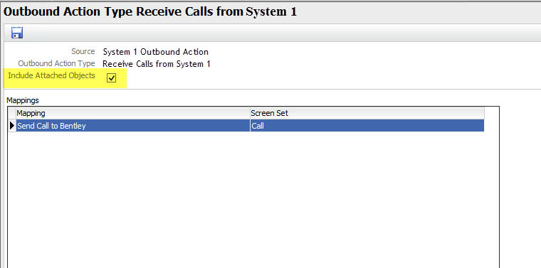
. - The Outbound Action Type [action name] window appears. Select the button on the toolbar.
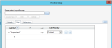
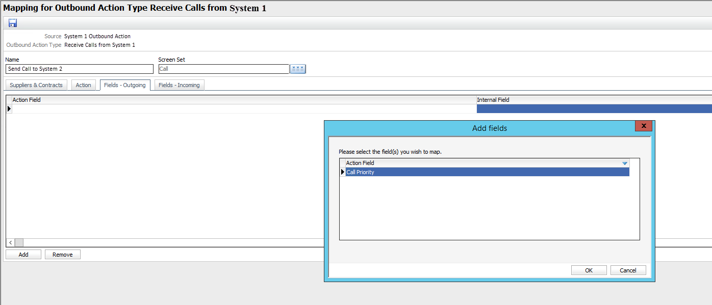
- In the Mapping window, complete the details.
- To associate an external supplier and contract with the Outbound Action mapping, select the Suppliers & Contracts tab.
- Select Add to add the supplier and/or contract to the browse table. Whenever a call or External Supplier task is forwarded to that external supplier and/or contract, this Outbound Action mapping will be applied.
-
You cannot specify the same supplier and contract (per screen set) for more than one Outbound Action mapping. However, you can link an external supplier to one mapping and the same supplier plus a contract to another mapping. In this case, the most specific mapping will be applied: if the call or task is forwarded to a supplier and contract matching the supplier and contract specified on the second mapping, this mapping will be applied. If not, it will use the default mapping for that supplier.
- Select the Action tab and ensure that the rules for Incoming and Outgoing Transactions using this mapping are as wanted.
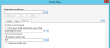
- Select the Fields - Outgoing tab and select Add. Complete the details.
- Select the Fields – Incoming tab and select Add. Complete the details.
- Your Fields - Incoming tab should look like this -
 .
. - Save the mapping and the outbound action.
| Name | Type a name for the mapping. This name appears in the Mappings table. | ||||
| Screen Set |
Select a call or External Supplier task screen set from the multi-tiered list. The screen set determines the fields that will be available for this mapping under the Fields – Outgoing and Fields – Incoming tabs.
|
If you change the screen set after defining outgoing or incoming field mappings, a warning appears indicating that some field mappings may become invalid.
| External Supplier | Select a supplier |
| Contract | Select a contract. If you do not specify a contract, the Outbound Action will be matched by the external supplier only. |
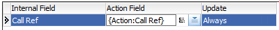
| Action Field | Select Call Ref |
| Internal Field | Select Call Ref |
Your Fields - Outgoing tab should look like this - 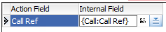 .
.
| Internal Field | Select Call Ref |
| Action Field | Select Call Ref |
| Update | Select Always |
Examples of Outbound Action Field Mappings
The following examples illustrate some of the more commonly used outbound action field mappings.
Transferring attachments from System 1 to System 2
- Add IntegrationAttachmentsEnabled=1 registry value in ASM Core/System level for both systems.
- Enable attachments in the Outbound Action mapping screen in System 1.

- When user attaches an object to a Call in System 1 this should be transferred to the call logged in System 2.
Max Object size should be considered here in System Settings (Admin). 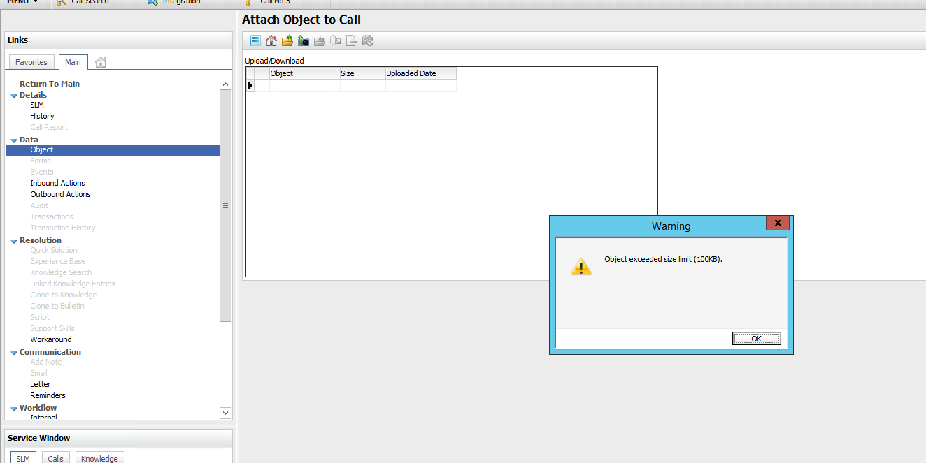
Profile mapping (dropdown)
- Expose the drop down field in System 2 – Inbound Action mapping screen.
- Save the Inbound Action.
- In System 1, open up the Outbound Action mapping page and map in the drop down selected in System 2.
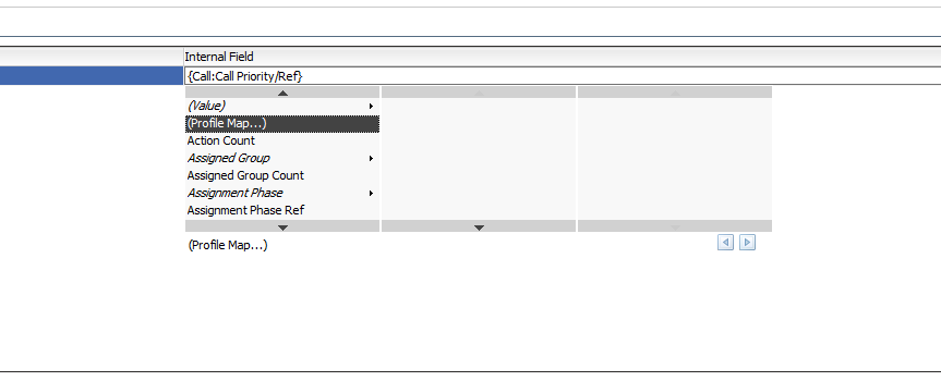
- Select Profile Mapping from Internal Field option.

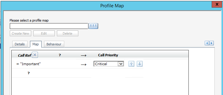
- Set up the Profile mapping.
- Save the Profile mapping


Transferring single values
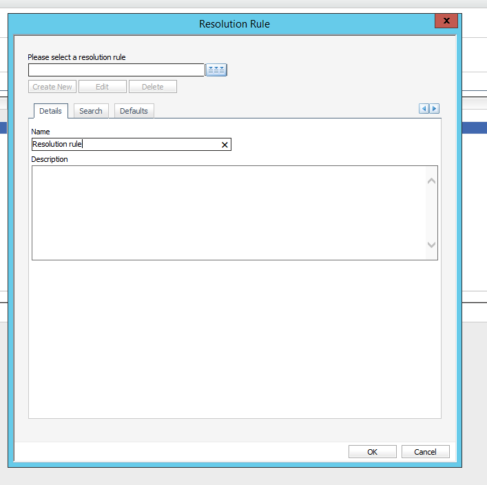
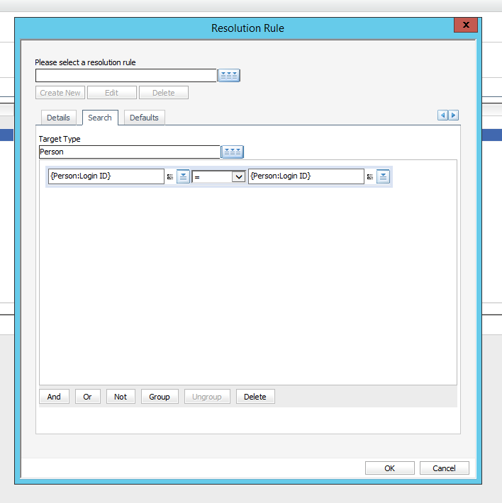
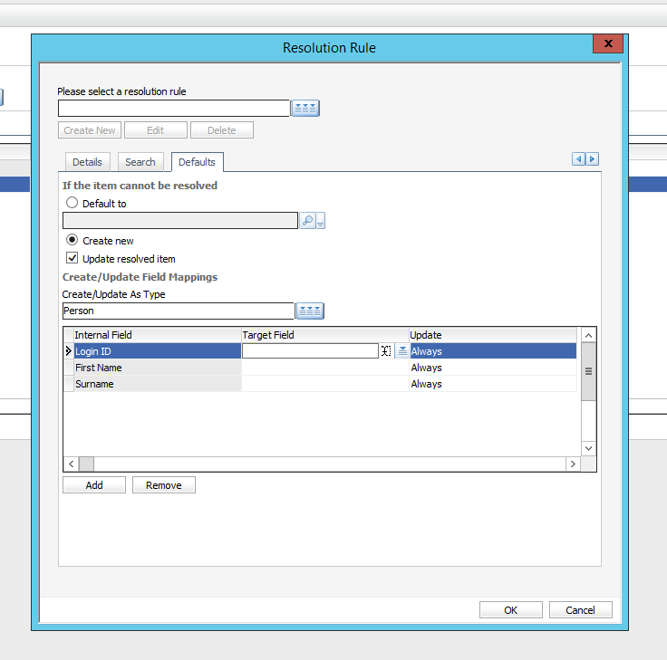
- Expose a single field in System 1’s Outbound Action mapping page/Fields – Incoming tab.
- Set up a Resolution rule. The rule should create an entity (e.g. User) in System 2 when a call is logged and transferred from System 1.


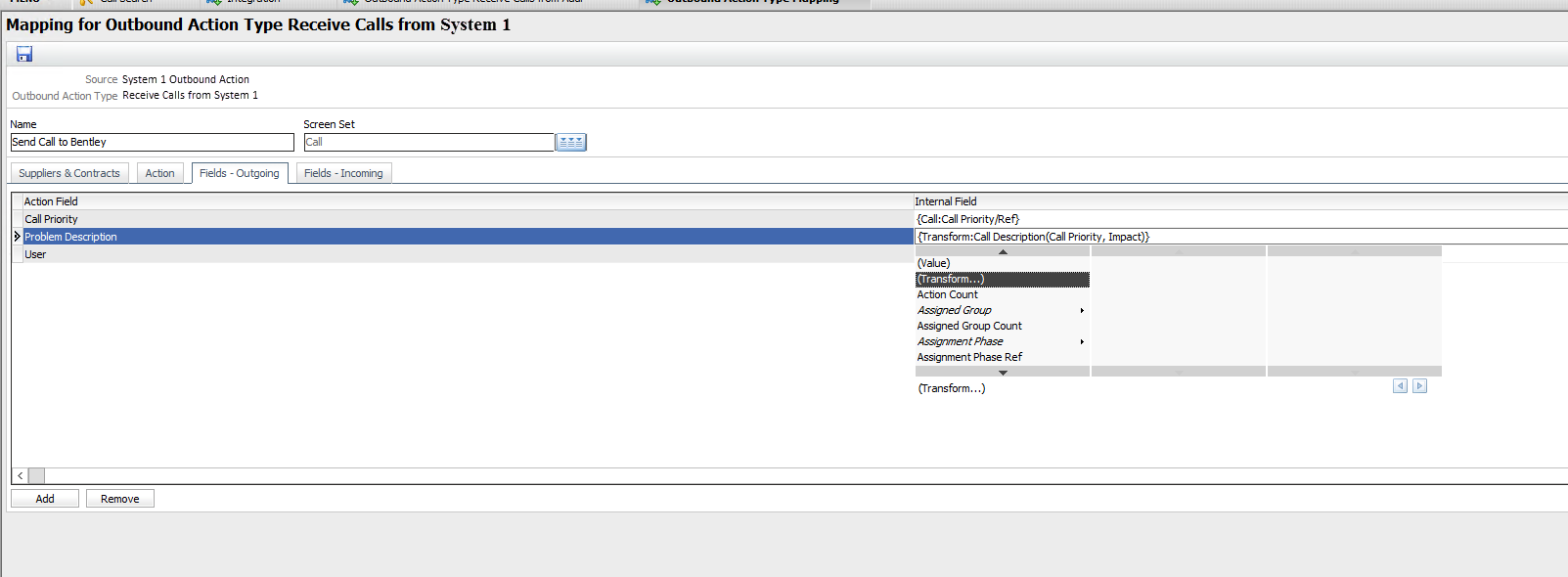
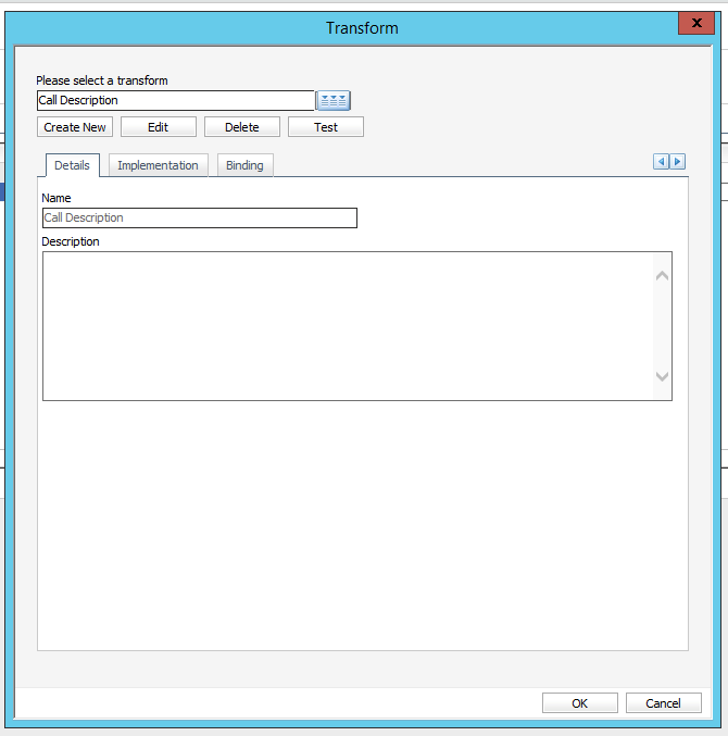
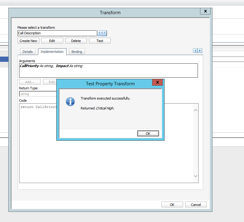
Using Transforms
Transforms are used to modify data and populate a field with the modified/converted data, e..g concatenate two field values and populate a field with the results. See screenshots below.
Ongoing Operation
Once the interoperability has been set up, there are two main ways to use this functionality.
Call Transfer
Follow these steps to transfer a call from the Creator system to the Receiver system:
- Open the call that is intended to be transferred.
- Click External to forward the call externally.
- Specify the External Supplier and the Contract as defined in the Receiver system settings
 . SeeConfiguring the System for Outbound Actions.
 - Click Forward to Supplier to transfer the call to the Receiver system.
- Once the call has been transferred, a button labeled Take Back is visible on the Call Details page. This button allows for the cancellation of the transfer of the call and disables the reconciliation of call information between the two systems. What happens to the call created on the Receiver system depends on the settings of the Receiver system.
The connector allows for objects attached to calls on the Creator system to be copied over to their related calls created in the Receiver system.
Workflow Tasks
Two workflow tasks can be used to trigger actions in the Receiver system:
|
External Supplier task |
Specific external supplier and contract pairs have to be detailed before the External Supplier task can be executed. In this case, settings for field mappings defined in the Outbound Actions page of the Integration platform are used when information are transferred to the Receiver system. |
|
Outbound Action task |
Enables the choice of a source and an action, as well as to define a task-specific mapping to be used by the selected action. The list of possible actions for this task reflects what has been defined as Inbound Actions by the Receiver system. |
Linking an Analyst to a Contract
You may discover that when you forward the call externally and select the External Supplier and contract that no analysts are available to forward the call or task. To resolve this:
- Create an external contact.
- Link the contract to the external contact.
- Link the contract to all analysts who will be externally forwarding the call.